Wavephotonics YAMLs: component#
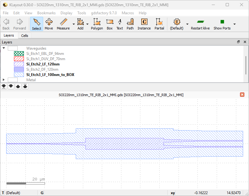
Below is the breakdown of an exemplary YAML file for a component, a 1x2 MMI, which has one input and two output ports, all optical. The original component file can be found here
First, let’s define the name of the file.
name: SOI220nm_1310nm_TE_RIB_2x1_MMI
This should be identical to the GDS file name (without the file extension). Continuing with the component type,
component_type: MMI1x2
component_type is not allowed to be arbitrary within the Wavephotonics’ YAML format - these are specified in the allowed list of components . Another requirement from Wavephotonics is explicit specification of the modes going through the ports.
modes:
  - mode_numbers:
    - 0
    - 0
    polarisation: TE
    wavelength: 1310
Here, we have defined modes, which has only one mode entry, TE_00 mode at 1310nm wavelength. When defined globally for the component this way, the modes field will be assigned to all the ports of the component. We move on to defining the ports:
ports:
- name: o1
  port_type: optical
  center:
  - 0
  - 0
  orientation: 180
  cross_section: rib_1310nm_TE
- name: o2
  port_type: optical
  center:
  - 123.6
  - 1.52500
  orientation: 0
  cross_section: rib_1310nm_TE
- name: o3
  port_type: optical
  center:
  - 123.6
  - -1.525
  orientation: 0
  cross_section: rib_1310nm_TE
Here, we defined the three ports within this MMI. First port o1 is the input port, and is facing the -x direction, hence its orientation is 180. It has a cross-section rib_1310nm_TE, which will be described in */cross-sections/cross_sections.yaml - it will be presented as a cross-section example later on. Ports o2 and o3 are outputs, they face +x direction (0 degree orientation), with their centres offset by 1.525 um from y=0 line.
Below we demonstrate port-level mode definition within a grating coupler’s YAML. The component is a 1D grating coupler for c-band operation in SiN - the original component file can be found here
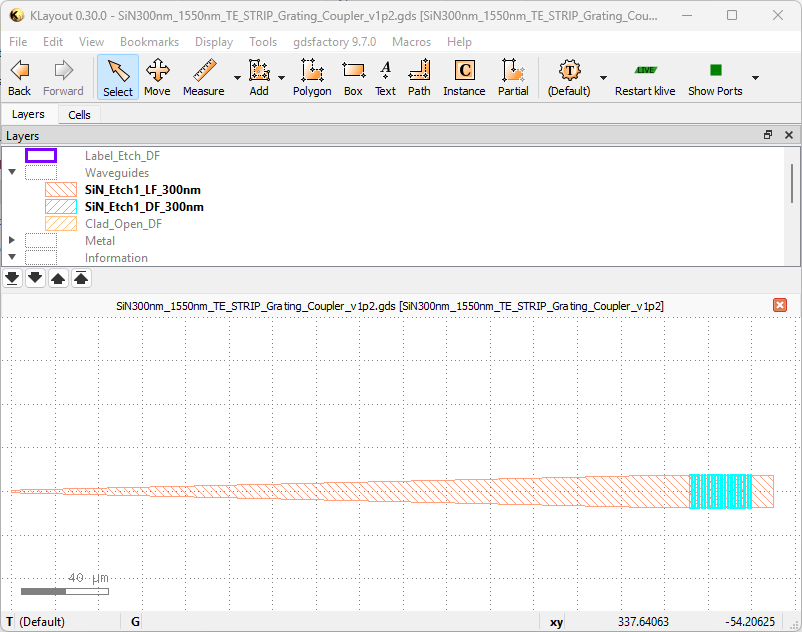
name: SiN300nm_1550nm_TE_STRIP_Grating_Coupler_v1p2
component_type: GratingCoupler1D
ports:
  - center:
    - 0.0
    - 0.0
    name: o1
    orientation: 180
    port_type: optical
    cross_section: strip_1550nm_TE
    modes:
    - mode_numbers:
      - 0
      - 0
      polarisation: TE
      wavelength: 1550
We defined the first port, an optical port with cross-section strip_1550nm_TE and facing -x. It is defined for TE_00 mode at 1550nm: modes went a level down in hierarchy to be a field of ports. The second port is a vertical port, which requires a different set of fields
ports: # Kept here to display the indentation - this line does not exist in the original file
  - center:
    - 325.81
    - 0
    name: vertical_te
    port_type: vertical_te
    orientation: 0.0
    width:  10.0
    coupling_angle_cladding: 13.659
    fibre_modes:
    - fibre_type: SMF-28
      wavelength: 1550
Here,
port_typeis specified asvertical_tefrom the allowed list of ports .For vertical ports, we are allowed to define a
widthinstead of across-section- e. g.10.0here.Another important parameter is
coupling_angle_cladding- this is the relative angle of the light travelling within the cladding. This component was designed for a 20 degree fibre angle over SiO2 cladding, hencecoupling_angle_cladding = arcsind(sind(20)*n_air/n_siox) = 13.659. If the device had been air-clad,coupling_angle_claddingwould have been set to20.0.Lastly, we defined
fibre_modesto specify the possibly different fibres to be used across different settings; i. e. it is possible to use780HPfor 780nm operation andSMF-28for 1550nm operation over the same grating coupler by defining an additional entry tofibre_modes, using the fibres listed in the allowed list of fibres.